
Making a Self Driving Car - Part 1
Published:
I just graduated from the University of Pittsburgh and have some time to relax before starting my job, so my dad and I decided to build a self-driving car. We think we can do it, and even if we can’t, at least we’ll learn some cool stuff while doing it. The goal is to start simple and build as we go.
Step 1 - Car Data
Before doing anything in the world of machine learning, we need to:
- Understand the problem.
- Understand the required data.
- Get the data.
Since we’re starting very simply, we aimed to create a self-driving car that would simply look at the road and turn the steering wheel by itself. We would manually provide braking and acceleration as needed. But first, we need a lot of training data. There is a terrific paper by NVIDIA titled “End to End Learning for Self-Driving Cars” that details a very simple self-driving car. It relies on camera input and the angle of the steering wheel as inputs to a CNN, which produces steering angle as an output. Let’s work on getting the steering angle!
CAN Bus
Modern cars are computers with wheels. Made up of many microcontrollers and ECUs (engine control units) that all control various systems in the car, from the engine and the drivetrain to the infotainment systems and the air conditioning. These controllers read and write data to their connected systems in order to control the car.
Having so many systems is a networking nightmare. Data has to be sent around the car since it is used in multiple places, which means miles of wiring underneath the car. This is not only inefficient, but also cost ineffective. To solve this issue, the CAN Bus was created.
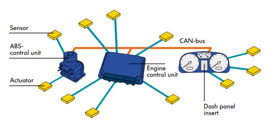
Image obtained from Volkswagen Audi.
(Note: the following is not a comprehensive CAN guide, it’s just enough to give you the gist of what’s going on! I learned the majority of this from Wikipedia, car repair manuals, and this wonderful presentation by Volkswagen Audi.)
CAN, standing for controller area network, is a protocol in which all control units in the car send digital signals over a copper wire bus (in the future, this will be fiber optics) at a max rate of 1,000 kbps. There are generally three separate CAN systems in a modern vehicle:
- High-speed drive train CAN Bus generally operating at 500 kbps (500,000 baud).
- Brakes, steering wheel angle, ECUs, etc.
- Low-speed infotainment CAN Bus generally operating at 100 kbps (100,000 baud).
- Radio, navigation, etc.
- Low-speed convenience CAN Bus generally operating at 100 kbps (100,000 baud).
- A/C, seat memory, etc.
The CAN bus works like an argument at a bar: everyone has stuff to say, so everyone starts yelling at once. Whoever starts yelling first wins after a bit and everyone stops talking and listens to them till they’re done, and then the yelling starts again.
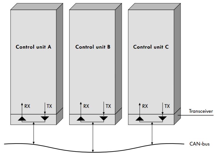
Image obtained from Volkswagen Audi.
There are two states the CAN bus can be in: low (0V, dominant) and high (5V, recessive). When no one is yelling, the CAN bus will read 5V, otherwise there will be constant digital chatter. Each message carries a specific format which I will not go into, but all we need to know is that:
- All messages are sent to all control units, aka, CAN is a broadcast system.
- Messages are filtered by their message headers, indicating the type of information.
In short, this means that control units are aware that someone else is talking, but only actually listen to the conversations pertaining to them.
Snooping on the CAN
Now that we know that our desired steering wheel angle data is to be obtained from the CAN Bus at 500,000 baud, we have to snoop on the CAN Bus to listen to all device chatter and intercept the message header pertaining to the steering wheel angle.
As of 1996, every car in the US is required to be shipped with an OBDII (on-board diagnostics v2) port. This connector has 16 pins, but most importantly, it has two pins for CAN High and CAN Low.
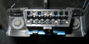
OBDII port. Image obtained from obd2allinone.com.
My thought was that if I could hook up a serial DB9 cable to those pins in my 2000 Toyota Camry’s OBDII port, I could read the CAN signals on my laptop and record all the data. Using the following pinout, I built the franken-cable (note to kids: this is super hacky and a piece of paper is not proper shielding).
| Pin description | OBDII | DB9 |
|---|---|---|
| Chassis Ground | 4 | 2 |
| Signal Ground | 5 | 2 |
| CAN High | 6 | 3 |
| CAN Low | 14 | 5 |
| Power | 16 | 9 |
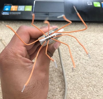
Horribly compressed image of the franken-cable. Use at your own risk.
Check Your Assumptions
This method would have worked had it not been for the fact that my 2000 Toyota Camry does not have a CAN Bus. Since the CAN Bus was widly adopted into cars around 2006, my car is too old to have this technology. Hell, it has relatively no electronics compared to cars of today. It’s smart to check your assumptions before diving all in. However, all is not lost. We plan on attaching a tilt sensor to the steering wheel and getting steering wheel angle data through that. To do this, we plan on introducing a Raspberry Pi to the car that will not only take in the tilt sensor data, but also interface with cameras and process their data at hopefully near 30 FPS to provide a near real-time data pipeline.
More to come as we tinker around!